¶ 2.1 · Node voltage with multiple sources
فارسی · Curriculum · Week 5 guide · Course index
¶ Learning goals
Label nodes against a common reference, write a signed KCL equation with several branches, and use its solution to determine actual current directions. Check the result with KCL, power and a useful bound. We use ideal DC sources and positive, constant resistances.
¶ From a circuit drawing to one equation
Week 4 introduced node voltage for a divider. A second source branch can feed the node or receive current from it. Even when the sources share a reference, their series resistors usually prevent you from reducing the network to a single series chain. Identify which terminals are joined by ideal wires. Every point on the same uninterrupted wire has the same node voltage.
Choose the common return as 0 V and label the unknown node v. If the far end of a resistor R is at a known voltage Vₖ, a current arrow drawn from v toward that end gives Iₖ = (v − Vₖ)/R. A negative value means actual current flows opposite the arrow. Use that same signed expression in KCL. Changing a minus sign after deciding which direction seems plausible would count the direction twice.
A resistor to ground contributes v/R. Let J be the current injected into the node by an independent source, with a sink represented by negative J. Then the sum of the outgoing resistor currents equals J. Expanding gives the following recipe.
v = (Σ GₖVₖ + J)/(Σ Gₖ), where Gₖ = 1/Rₖ.
Use volts, kilohms, millisiemens and milliamps consistently. For example, 1/(6 kΩ) is 1/6 mS, and 3 V across 6 kΩ gives 0.5 mA. Multiplying mS by volts gives mA, so the numerator above is a current. Dividing by total conductance gives volts.
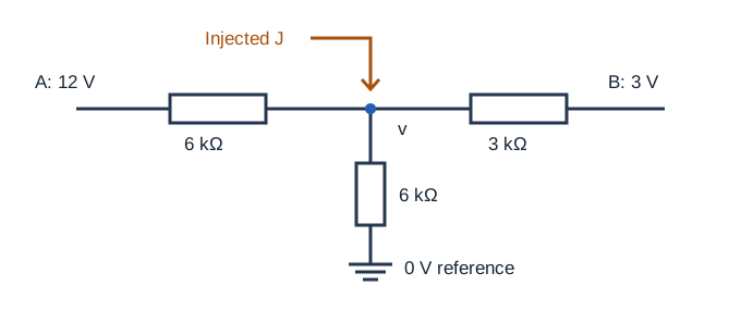
¶ Example 1 · Two voltage branches and a load
Connect node v to 12 V through 6 kΩ, to 3 V through 3 kΩ, and to ground through 6 kΩ. Let J = 0. With all resistor arrows leaving v, KCL in mA is (v − 12)/6 + (v − 3)/3 + v/6 = 0. Multiplying by 6 gives 4v − 18 = 0, hence v = 4.5 V.
| Branch | Signed current leaving v | Actual direction |
|---|---|---|
| 12 V rail | −1.25 mA | Into v |
| 3 V rail | 0.5 mA | Toward the 3 V rail |
| Ground | 0.75 mA | Toward ground |
Check −1.25 + 0.5 + 0.75 = 0 mA. The 12 V source delivers 15 mW. The 3 V source absorbs 1.5 mW because current enters its positive terminal. The resistor losses are 9.375, 0.75 and 3.375 mW, a total of 13.5 mW. Together the receiving source and the resistors account for 15 mW.
¶ Example 2 · Add current injection
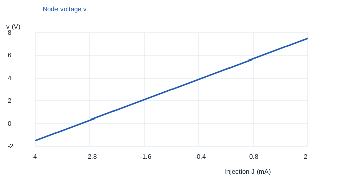
Keep the three resistor branches and inject 1 mA from ground into v. The expanded equation is 4v − 18 = 6, giving v = 6 V. The outgoing resistor currents are −1, 1 and 1 mA. They sum to 1 mA, matching the source injection. The total conductance is 2/3 mS, so a 1 mA increase in injection raises the node by 1.5 V. The current source arrow determines the sign of this change.
¶ Example 3 · A sink pulls the node below ground
Replace the injection with a 4 mA sink. Now J = −4 mA and 4v − 18 = −24. The result v = −1.5 V is physically consistent for the ideal model. Resistor currents directed out of the node are −2.25, −1.5 and −0.25 mA. Their sum is −4 mA, so the resistor network supplies the sink. Even the ground branch carries current toward v because its far end is at the higher potential, 0 V.
Without current injection, the equation is a weighted average of the attached voltages, with positive conductances as weights. That gives a quick bound between the smallest and largest rail values. Example 3 shows why this bound cannot be applied after adding a current source.
¶ Example 4 · Increase the load
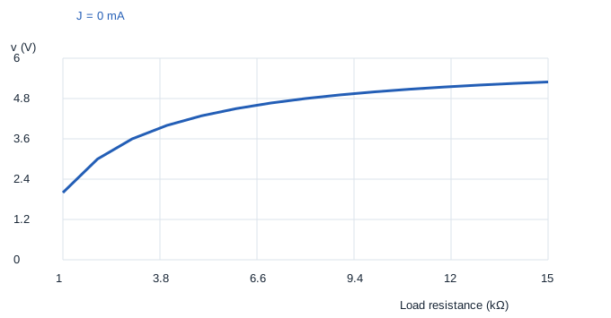
Restore J = 0 and change only the load to 3 kΩ. The equation becomes (v − 12)/6 + (v − 3)/3 + v/3 = 0, so 5v = 18 and v = 3.6 V. The currents are −1.4, 0.2 and 1.2 mA. A smaller load resistance gives ground more weight in the node equation and lowers the voltage. The loaded voltage fell while load current increased from 0.75 to 1.2 mA.
¶ Practice
Solve 1–6 independently. Problems 7–8 are optional.
- Connect v to 9 V through 3 kΩ and to ground through 6 kΩ. Write KCL and find v and both currents.
- In Example 1 change the 3 V rail to 6 V. Find v and all branch currents.
- In Example 1 inject 2 mA. Find v and verify the outgoing sum.
- In Example 1 find the injection that gives v = 0.
- In Example 1 open the ground resistor branch. Find v and verify the two resistor currents.
- Connect v to 8 V through 2 kΩ and to ground through 2 kΩ. Add a 1 mA sink. Find v and check KCL.
- With no injection, explain how a resistor changed toward zero would affect v, assuming the other resistors stay fixed and positive.
- In Example 1 find the injection for which the 3 V branch carries zero current. Explain how you know its direction reverses there.
¶ Worked answers
- (v − 9)/3 + v/6 = 0 gives v = 6 V. The outgoing currents are −1 and 1 mA.
- 4v − 24 = 0 gives 6 V. The currents are −1, 0 and 1 mA.
- 4v − 18 = 12 gives 7.5 V. The currents are −0.75, 1.5 and 1.25 mA, which sum to 2 mA.
- Substitution gives J = −12/6 − 3/3 = −3 mA. A sink is needed.
- (v − 12)/6 + (v − 3)/3 = 0 gives v = 6 V. The two currents are −1 and 1 mA.
- (v − 8)/2 + v/2 = −1 gives v = 3 V. The currents −2.5 and 1.5 mA sum to −1 mA.
- That branch’s conductance grows and dominates the weighted average. The node approaches its far-end rail voltage.
- Zero current means v = 3 V. KCL then gives J = −1 mA. Increasing J increases v, so the difference v − 3 changes from negative to positive across that setting.
Common errors: mixing volts and ohms with an mA current, treating a sink as positive injection, and assuming that a voltage source always supplies power. Start each solution by writing the reference, current arrows, units and sign of J.