¶ 2.2 · Superposition in DC circuits
فارسی · Curriculum · Week 6 guide · Course index
¶ Learning goals
Separate the signed voltage and current contributions of independent sources. Use one KCL equation to check the sum and compute resistor power from the final current or voltage.
¶ Why it works
For an ideal resistor, current is proportional to the voltage difference. For the network below, define the reference as ground and all resistor currents as leaving node v. A positive current source J injects current into v. Using volts, kΩ, and mA gives
(v − VA)/4 + (v − VB)/8 + v/8 = J
Group the coefficients of v. The total conductance is 1/2 mS, so
v = VA/2 + VB/4 + (2 kΩ)J
The first two coefficients are dimensionless. For the final term, kΩ × mA gives V. The separation comes from linearity: the same conductance multiplies v in each case. For every case retain the resistors and the reference directions. An inactive ideal voltage source is set to 0 V, so its terminals are shorted. An inactive ideal current source is set to 0 A, so its branch is opened. These are analysis steps for an ideal model. Never short a physical power supply.
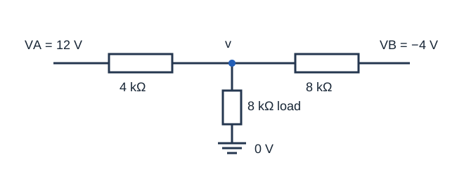
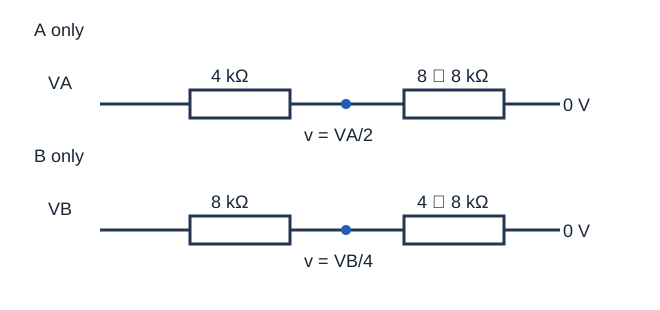
The original circuit is shown with both sources active. In the A-only circuit, replace the VB source with a wire while keeping the 8 kΩ resistor. The two 8 kΩ paths to ground then make 4 kΩ in parallel, so VA drives an equal 4 kΩ divider. In the B-only circuit, keep the 4 kΩ branch to ground when setting VA to zero. It parallels the 8 kΩ load, giving 8/3 kΩ to ground and a divider ratio of 1/4 for VB.
¶ Four worked examples
¶ 1 · Opposing voltage sources
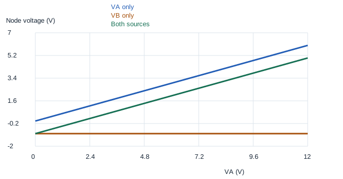
Set VA = 12 V, VB = −4 V, and J = 0. A alone gives 6 V and B alone gives −1 V. The sum is 5 V. Check the original circuit: the outgoing currents are (5 − 12)/4 = −1.75 mA, (5 + 4)/8 = 1.125 mA, and 5/8 = 0.625 mA. Their sum is zero. The negative sign means the A branch supplies current into v.
¶ 2 · Include a current source
Keep the two voltages and let J = 1 mA. With both voltage sources set to 0 V, the three resistors have a combined conductance of 1/2 mS. The current source alone raises the node by 2 V. The total is 7 V. The outgoing currents are −1.25, 1.375, and 0.875 mA, which sum to the injected 1 mA. Changing J to a 1 mA sink would instead contribute −2 V.
¶ 3 · Cancellation
Keep VB = −4 V and J = 0. At VA = 2 V, the separate contributions are +1 and −1 V. The load current is zero because its terminals are at the same potential. The source branches still carry −0.5 mA and +0.5 mA. A zero node voltage does not establish that all branch currents are zero. The green sweep trace crosses zero at 2 V.
¶ 4 · Compute power after adding
Return to VA = 12 V and VB = −4 V. The load voltage is 5 V, so its power is 25/8 = 3.125 mW. Squaring the separate voltages gives 36/8 + 1/8 = 4.625 mW. This is wrong because (6 − 1)² includes the cross term −12. Use superposition for linear quantities, then use the combined value for power.
¶ Check your reasoning
Follow the same reference arrow for each branch in every case. Add signed values. Before using superposition, check that the model is linear and the circuit connections and component values stay the same across cases. Use an independent KCL check when signs are unclear.
¶ Practice and worked answers
All questions use the 4, 8, and 8 kΩ network. Set J = 0 unless specified.
- Find v for VA = 8 V, VB = 4 V. Answer: Add 4 and 1 to get 5 V.
- With VA = 0 and VB = 8 V, find the load current toward ground. Answer: v = 2 V, so 2/8 = 0.25 mA.
- Find the load current for VA = 4 V and VB = −8 V. Answer: The contributions +2 and −2 V cancel, giving 0 mA.
- With both voltages zero and J = −0.5 mA, find v and explain the sign. Answer: v = −1 V. The sink pulls the node below the reference.
- For VA = 12 V and VB = −4 V, find J for zero load current. Answer: The voltages give +5 V, so 5 + 2J = 0 and J = −2.5 mA.
- At VA = 0 and VB = −4 V, check signed KCL. Answer: v = −1 V and the outgoing currents are −0.25, +0.375, and −0.125 mA. They sum to zero.
- At VA = 8 V and VB = 4 V, find load power. Answer: v = 5 V and P = 25/8 = 3.125 mW. The partial powers 16/8 and 1/8 omit the positive cross term.
- Keep VB = −4 V. By how much does the load current change when VA rises from 2 to 6 V? Answer: v rises from 0 to 2 V. The signed load current rises by 0.25 mA.